Parcel maps
Types of parcel maps
Innobrix lets you add several types of underlays to your project or plan. Not all types are available in every project type. There are four variants:
2D underlay
The 2D underlay is the most common. It is a 2D image in .jpg, .jpeg, .png, or .svg format.
- Maximum resolution:
4096px x 4096px.
Pay attention to dimensions and file size. The values above are not hard limits. Larger files are accepted, but load time and performance may suffer.
Importing the 2D underlay
The simplest way is to drag the underlay into the 3D scene from a folder on your computer.
Alternatively, right-click Layers under Parcel map in the Scene hierarchy or use Alt + T.
-
BIM Publisher
-
Home Configurator
-
Plan Configurator (step 2)
Terrains
A Terrain (formerly 3D parcel map) is less common but allows depth effects like landscape slopes. The 3D map appears as Parcel map model in the scene hierarchy. Available Terrains can be dragged from the Content Browser under Terrains into the 3D scene to replace the default purple terrain. Only one 3D model can be assigned to a plan, but it can be combined with a 2D underlay on top.
Importing Terrains
Add 3D terrains in Innobrix Studio under Terrains.
Supported formats:
-
IBX
-
GLB
-
OBJ + .MTL (and textures)
You can then find them in the Content Browser under Terrains.
-
Watch for faces that are very close (e.g., ground level and a road). Too close can cause z-fighting (flicker).
-
Use clear material names on elements. A (red) brick road with material
Generic Models material #7F7F7FFis unclear. -
2D elements like model text, model lines, and other non-geometry annotations are not imported.
-
Please do not include decoration like trees/fences. Innobrix has its own optimized decoration module. Including such details can slow the configurator.
-
Materials are shared across all Terrains. The material "Gras" on "Model A" is the same on "Model B"; changes in one affect the other.
-
BIM Publisher
-
Home Configurator
2D plot selector
The 2D plot selector is a classic configurator approach: click a 2D image in the browser to go to the 3D home. It�s an alternative for large/heavy 3D projects, offering a better experience for users with modest devices or connections. It�s recommended for projects with more than 5 homes.
Do not confuse the 2D plot selector with the 2D underlay; they are different.
Setting up the 2D plot selector
To implement the 2D plot selector, first switch to 2D plot selector mode. In the Plan Editor, go to the 2D camera via the icon in the Top bar and click 2D.
You will see the screen below.
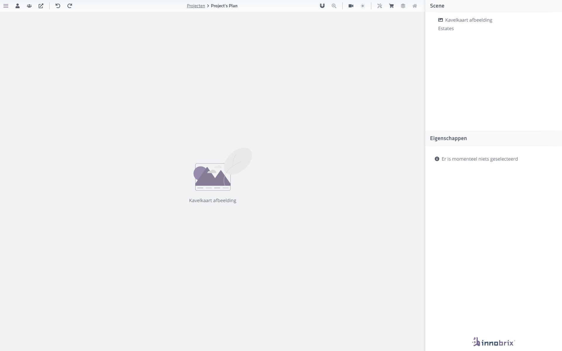
The 3D scene is replaced with a 2D image field.
Click the image field to upload an image.
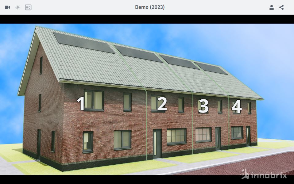
A Full HD image (1920 x 1080 px) is recommended. These are often AI-generated perspectives where all homes you want to outline are clearly visible.
For the next step fill in two properties for all Homes in your plan:
-
Name -
Innobrix construction number
The Name property shows the home in the Scene hierarchy.
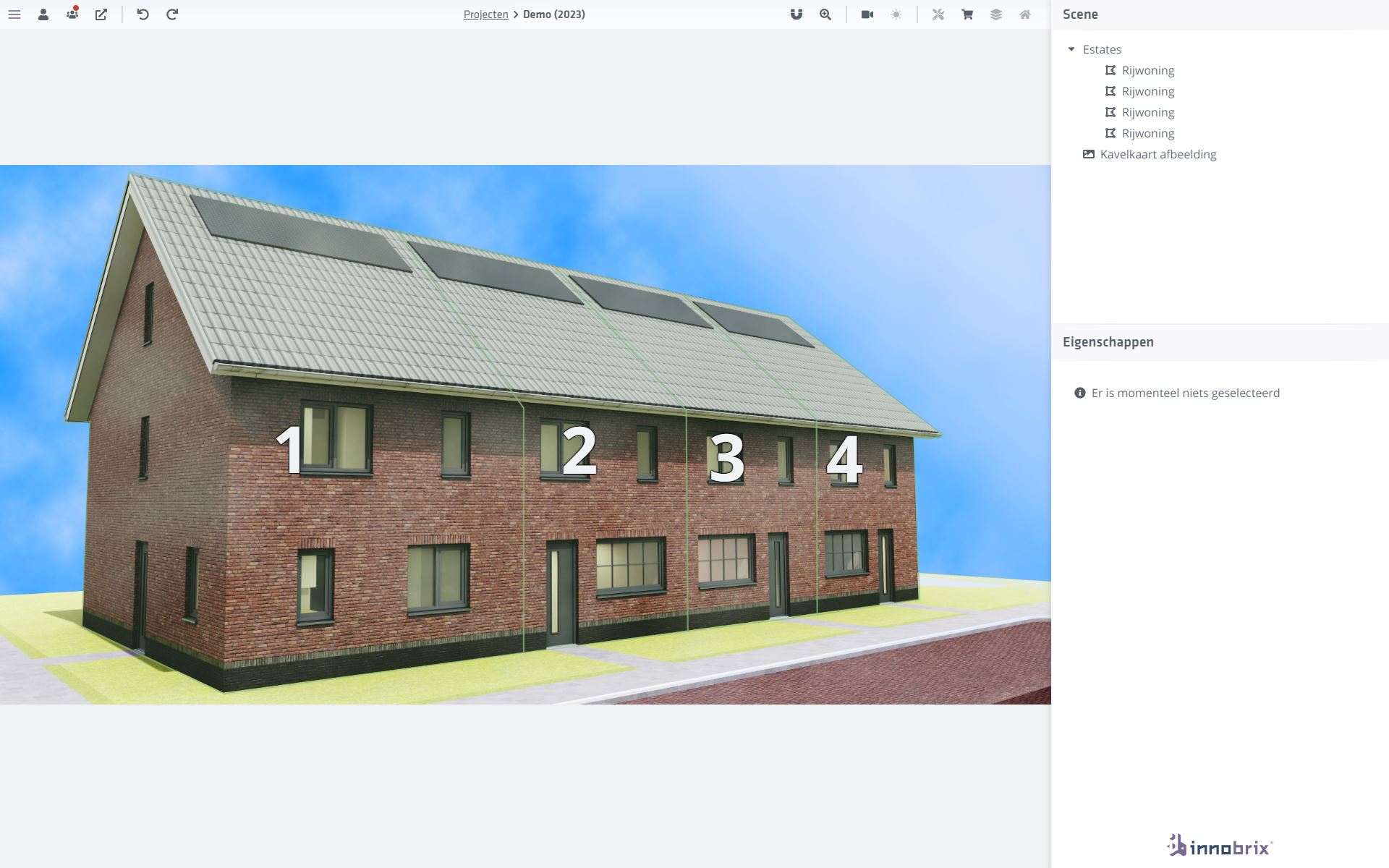
The Innobrix construction number appears at the center of the lines you draw, as shown below.
In the top bar you have extra tools helpful when drawing plot selectors:
The icon toggles point-to-point snapping.
The icon lets you zoom in further for precise point work.
Drawing the 2D plot selector
Once an image is loaded and Homes have a Innobrix construction number and Name, you can start outlining them by drawing polygons on the image.
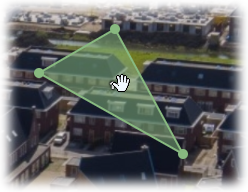
In the Scene hierarchy, select the lot/home. Then grab the green frame for that lot and move it to the correct region by clicking (near the center of the green frame) and dragging.
When satisfied with placement, you can:
-
Add a new point by hovering between two existing points until a new green point appears. Click (and drag to reposition) to add it.
-
Remove an existing point by selecting it (it highlights slightly) and pressing Delete on your keyboard.
-
BIM Publisher
-
Home Configurator
Map layers & 3D Bag data
Map layers and 3D-BAG data are underlays loaded from PDOK data. They are exclusive to the Plan Configurator.
In both the Plan Editor and Viewer of the Plan Configurator, you can switch map layers via the icon.
Available map layers:
-
Standard
-
BGT Background visualization
-
Satellite
-
Cadastral
3D-BAG objects can be toggled in the same menu.