Configurable & Model Editor
The Configurable-Editor and Model-Editor are the technical workshops and the underlying foundation of all projects. This is the place
where you further format and/or configure your exported BIM models.
Within the Model Editor
You can perform the following actions within the Model-Editor:
- Adjust various cameras
- Adjust materials*
- Upload textures.
- Perform model updates.
- Create and/or adjust floors*.
Within the Configurable-Editor
Create or import option lists
Execute the process of Option mapping
Set up option logic
Tuning different cameras
Modify or create materials
Create material changes
Upload textures
Make model updates
Create and/or adjust floors
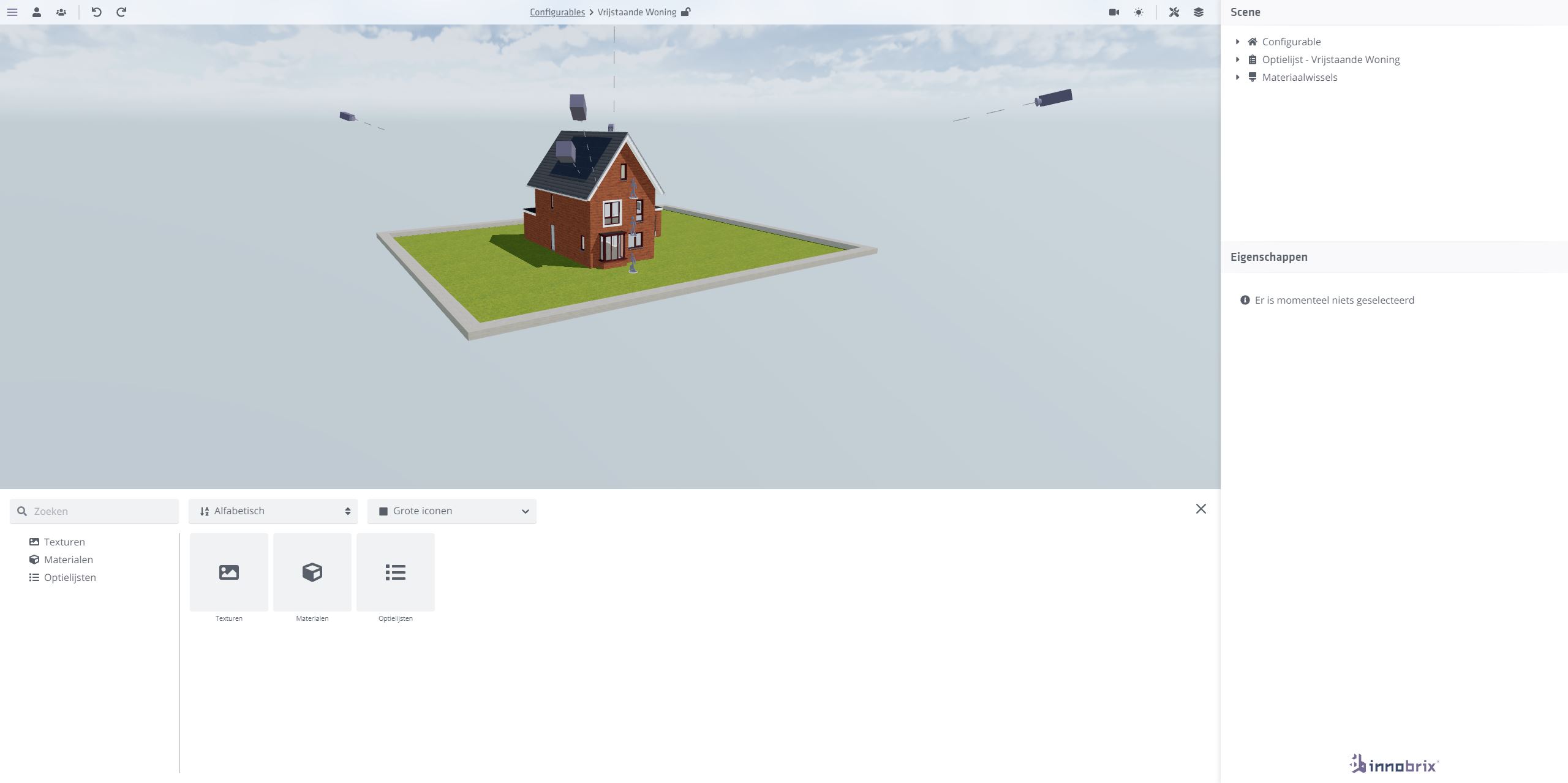
You can reach the Configurable or Model editor of a model by going to the Configurables or Models page and clicking on the thumbnail of a model.
Configurable-Editor
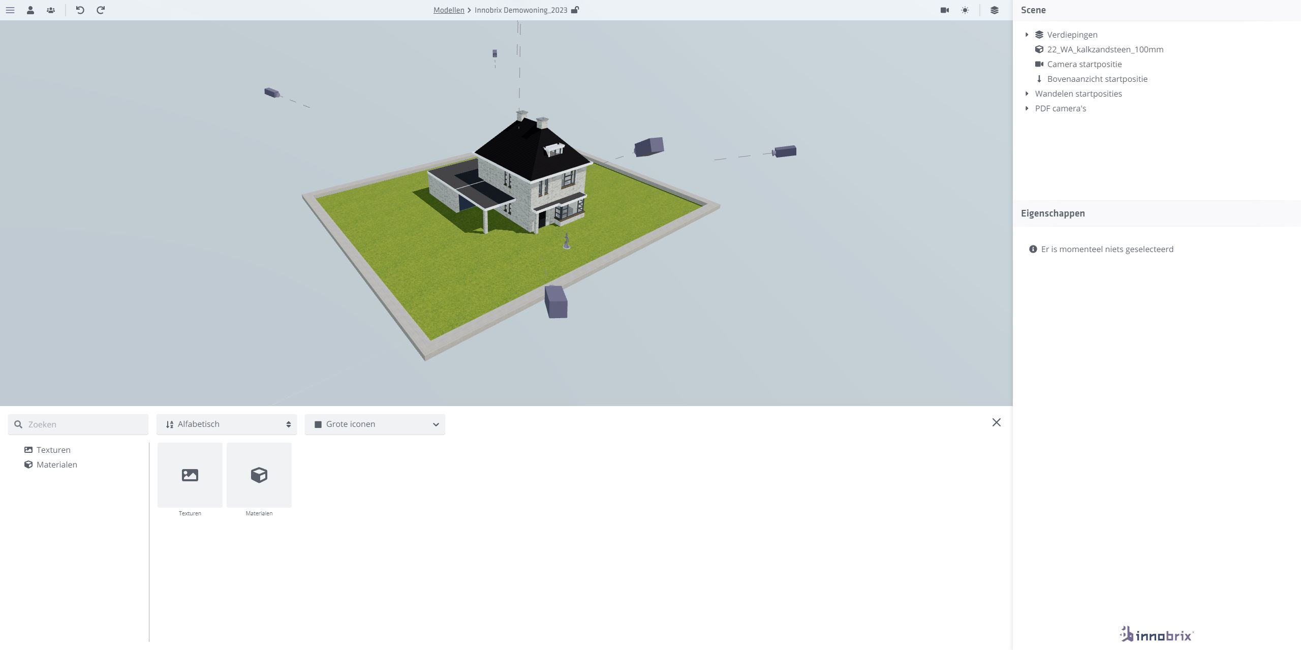
Model-Editor
The Configurable-Editor Toolbar
The Toolbar is found at the top of the screen and contains a range of different functionalities. Some of them,
such as for example the Sun Study icon are shared among several
editors (and often the Innobrix Viewer as well).
![]()
However, within the Toolbar are 2 menus exclusive to the Configurable-Editor environment.
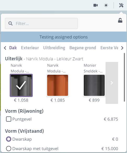
Configurable-Test menu
You can use this menu to test the model with when you are doing the
process of option logic and option mapping.
You can use the icon to prevent the menu from closing as soon as you click something outside this screen. Finally
you can use the Filter menu to easily search for specific options in your options list, should you have many.
This menu is only available to the Configurable-Editor and only if the model is in collapsed state.
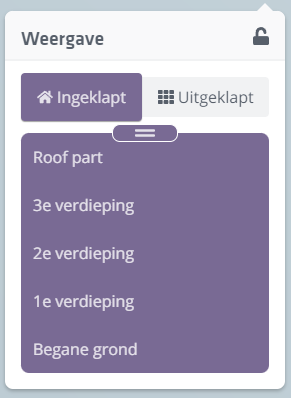
Floor switcher menu.
This menu can be used to view sections of the model. Exactly which Floors appear in this list depends
on exactly which floors are set.
It is possible to tug (click + drag) the slider to clip the house in real time. Additionally you can also click on a
specific floor to place the section at the height of the chosen floor.
Collapsed & Expanded.
These two buttons cause the model to be displayed in a composite view or in tas field view. The unfolded version can be used
for implementing options within the model.
This item is not available and present in the Model-Editor.
Scene hierarchy
The Scene hierarchy is found at the top of the right side of the screen and gives an overview of all the
components present in the Model-Editor and Configurable-Editor (but also the Plan-Editors have a scene hierarchy).
Model Editor:

- Configurable
- Option List - [name of linked option list].
- Material Changes
Configurable Editor:

- Configurable
- Option List - [name of linked option list].
- Material Changes
Configurable
The Configurable section contains all the parts directly related to your imported model. Under this section are the
Floors, Columns, the Camera Start Position, the Upper View start position, The Walk Mode (walk) start positions and finally the PDF cameras.
Floors
Here you will find all available floors that your model can use.
These are primarily taken from Revit, and are used to create the
Floor switcher to function correctly. The Floor Changer provides the horizontal cross-sections of the model.
The Floor Changer operates based on these levels and ensures that the correct elements are visible. However, the idea that when
one chooses the Ground Floor in the floor switcher, the horizontal section would set exactly at this height is not correct.
For example, the Ground Floor has an absolute height of 0, which would mean that if the house were cut at this height,
virtually nothing would be visible!
Thus, to ensure that elements are indeed visible in such a case, a modified formula is in use that determines at what height the house should be cut. The formula for this is as follows:
(Cut Height Storey) = P + (Cut Height Upper Storey) - (Floor Thickness Upper Storey)

(P = height of zero model)
Floor properties
Revit ID
The elementID of the corresponding 'level' in Revit. (Read-only)
Revit name
The name of the level as annotated in Revit. (Read-only)
Name
The name of the level as annotated in Innobrix. This field is freely customizable.
Height
The height of the floor as determined by Revit. (Read-only)*
It is possible to create your own (new) floor and adjust its height. Floors that have been created from an Innobrix import coming from Revit, however, are static and read-only.
Floor Thickness
Floor thickness is an adjustable property (and can be thought of as an offset) that is subtracted from the height of the related floor. This is necessary
to avoid facing a ceiling, for example, when using the Floor switcher by selecting a floor in it.
selected.
Create floors
It is possible to create your own floors within Innobrix where the Height is adjustable.
By right-clicking on Floors (found under the Scene hierarchy), you can create them.
The new floors is automatically added as the highest floor, with a height exactly 1000mm higher than the previous floor.
Disable or remove floors
There may be circumstances where it is undesirable to use all the floors that came along from Revit in the
Floor switcher. It may also be that, inadvertently, too many levels have been included (e.g. certain auxiliary levels that had Building Story checked during export).
were checked during export).
Based on this, it is possible to disable floors.
Open the Floors dropdown and place the cursor over a floors you want to disable. Click
then click the icon to disable the selected floor. All floors that have
have a visible icon are disabled and are no longer used in the
Floor switcher (and therefore not in the formula to calculate the section height).
Columns
This section of the Scene hierarchy refers to the completion of the Innobrix: Column parameter. For example, Column 0 is equivalent to.
Innobrix: Column: 0 for example. Columns can best be thought of as a kind of category.
Assign labels to columns
Labels can be used to quickly filter and search within a grid field. This is particularly practical when a model contains many Model Groups
and needs regular maintenance.
Note that this search functionality is only available when the model is in [unfolded view], and only with models
using the structure where there is no Innobrix: Floor parameter is present.
Row
Columns contain an x number of rows. Rows are the actual Model Groups exported from Revit. Clicking a Row from the Scene hierarchy is exactly the same
as clicking a group when the model is expanded.
Camera Start Position
The camera start position determines the camera position of this Configurable if the end user within the Viewer clicks on a Home (and then
view or configure one created based on this model. This camera also calculates, based on the orientation, the
'pivot point' of the model. While viewing in the Viewer, the camera will rotate around this point. The orientation of the camera
can be set manually through the Properties panel by entering position and rotation values.
An easier way to set this is the following:
- Rotate around the model and choose a nice vantage point.
- Then right-click
Camera Start Positionand selectCopy Position from Camera. You can also use the hotkeyAlt + Cfor this purpose.
 )
)
Top view camera start position
This camera determines the top view camera position when starting from the camera menu. The camera also offers a small preview here, and can be adjusted via the move tool or the -rotate tool, where the latter can only rotate about the Z axis. (It is, after all, a topdown camera).
Walking start positions.
The Walk mode or Walk mode positions can be set per floor here.
See also: Walking mode.
PDF cameras.
The PDF cameras are used while creating the screenshots for the automatically generated PDF, and are created based on the available
Floors created. Each camera provides a small preview, and is manually customizable by dragging the camera in the environment.
Normally this is not necessary unless the property has an unusual shape where the cameras are not positioned.
Note that it is not possible to disable the PDF cameras, or the automatic PDF as a whole. However, it is possible to add your own PDF brochure to this file via the Project Properties.
Option List
This entry within the Scene hierarchy contains the structure of a linked option list. Next to the term Option list, next to the dash -,
is the name of the linked option list. Below that, a number of properties are also visible. For example, there is also a (customizable) icon.
All available option lists can be found within the Content Browser, under the heading Option Lists.
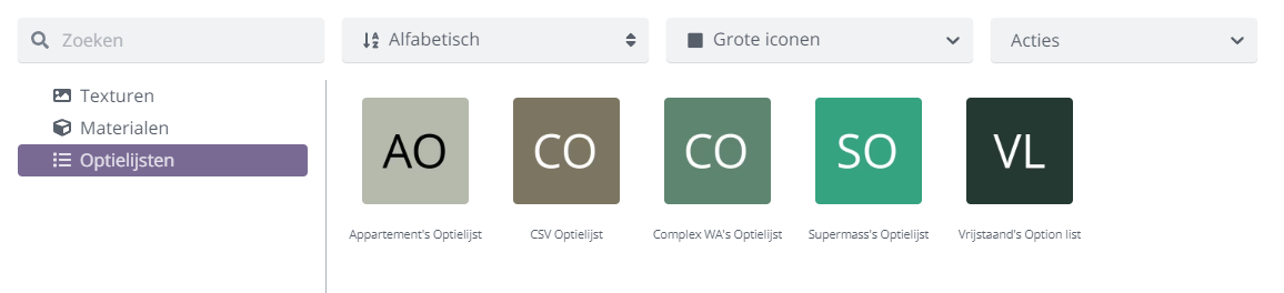
How to set up, import, export or link option lists is explained here.
Material switches
Material switches are linked to an option list and allow materials to be swapped.
See also: Material Switches